When it comes to installing a smart thermostat like Ecobee, understanding the wiring diagram is crucial. The wiring diagram will guide you on how to properly connect the Ecobee thermostat to your HVAC system, ensuring that it functions correctly and efficiently.
Before you begin the installation process, it’s important to familiarize yourself with the Ecobee wiring diagram. This diagram will show you which wires from your HVAC system need to be connected to the corresponding terminals on the Ecobee thermostat. This step-by-step guide will help you navigate through the installation process with ease.
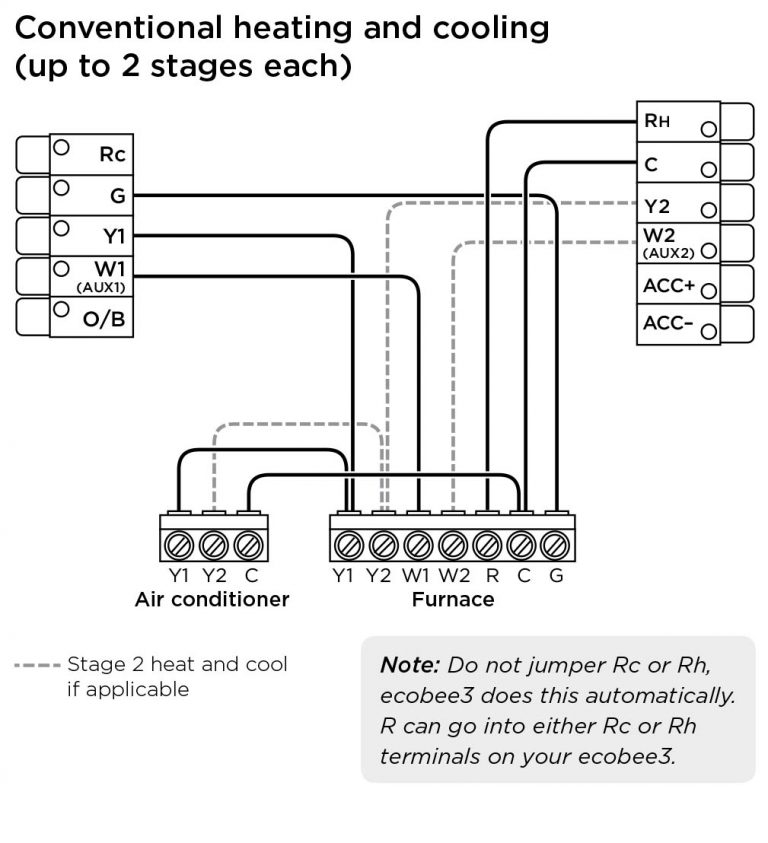
 Ecobee 4 Thermostat Wiring Diagram (stewart-switch.com)
Typically, the Ecobee thermostat will have terminals labeled R, C, W, Y, and G. The R wire is the power wire, the C wire is the common wire, the W wire is for heating, the Y wire is for cooling, and the G wire is for the fan. By following the wiring diagram provided by Ecobee, you can easily match the wires from your HVAC system to the correct terminals on the thermostat.
It’s important to note that if your HVAC system has a different wiring setup, you may need to consult a professional or refer to the Ecobee support resources for further guidance. Incorrect wiring can lead to system malfunctions and potential damage, so it’s essential to follow the wiring diagram carefully.
Once you have successfully connected the wires according to the Ecobee wiring diagram, you can proceed with the rest of the installation process. This may include setting up the Ecobee app, connecting the thermostat to your Wi-Fi network, and customizing the settings to suit your preferences.
In conclusion, understanding the Ecobee wiring diagram is key to a successful installation of your smart thermostat. By following the diagram and connecting the wires correctly, you can enjoy the convenience and energy-saving benefits that the Ecobee thermostat has to offer.