When it comes to networking, one of the most commonly used connectors is the RJ45. This connector is used for Ethernet cables, which are essential for connecting devices to a local area network (LAN) or the internet. To ensure proper connectivity, it is important to understand the wiring diagram for RJ45.
RJ45 connectors have eight pins that need to be wired correctly in order for the connection to work effectively. Each pin serves a specific purpose in transmitting data, and following the correct wiring diagram is crucial for optimal performance.
 Ethernet Coupler Wiring Diagram (wiringdiagramall.blogspot.com)
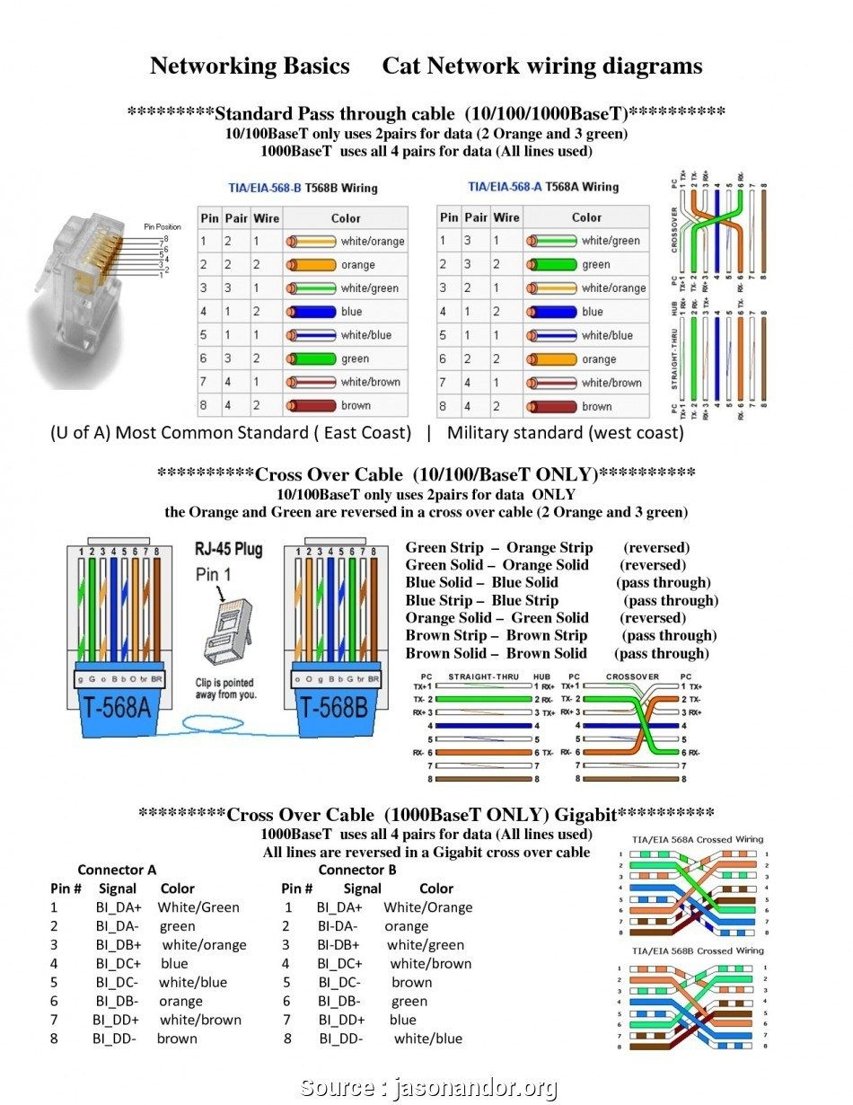
There are two main standards for wiring RJ45 connectors: T568A and T568B. Both standards are widely used and are compatible with each other, but it is important to choose one standard and stick to it for consistency.
When wiring an RJ45 connector, it is important to follow the color coding scheme for each pin. The standard color code for T568A is white-green, green, white-orange, blue, white-blue, orange, white-brown, and brown. For T568B, the color code is white-orange, orange, white-green, blue, white-blue, green, white-brown, and brown.
It is also important to use the correct tools and materials when wiring RJ45 connectors. A crimping tool, cable stripper, and tester are essential for ensuring that the connections are secure and properly configured. Additionally, using quality Ethernet cables and connectors will help prevent signal loss and interference.
In conclusion, understanding the wiring diagram for RJ45 connectors is essential for maintaining a reliable network connection. By following the correct color coding scheme and standards, you can ensure that your Ethernet cables are properly configured for optimal performance.