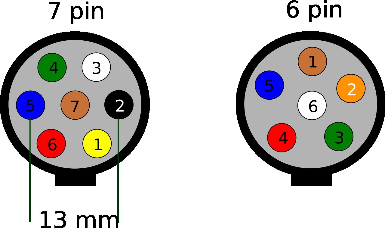
When it comes to towing a trailer, having the proper wiring setup is essential for safety and convenience. A 7 pin trailer socket is commonly used for connecting trailers to vehicles, allowing for the transfer of power and signals between the two. Understanding the wiring diagram for a 7 pin trailer socket is important for ensuring that all connections are made correctly.
Whether you are installing a new trailer socket or troubleshooting an existing one, having a clear wiring diagram can make the process much easier. By following the diagram, you can ensure that each wire is connected to the correct pin on the socket, preventing any potential issues with the trailer’s lights or brakes.
 7 Pin Trailer Wiring Diagram Wiring Diagram (www.autowiringdiagram.net)
Here is a basic wiring diagram for a 7 pin trailer socket:
Pin 1 – Yellow wire (Left turn signal and brake light)
Pin 2 – Blue wire (Auxiliary or reverse light)
Pin 3 – White wire (Ground)
Pin 4 – Green wire (Right turn signal and brake light)
Pin 5 – Brown wire (Tail lights)
Pin 6 – Red wire (Brake lights)
Pin 7 – Black wire (12V power supply)
It is important to note that the color coding of the wires may vary depending on the manufacturer, so always refer to the specific wiring diagram for your trailer socket. Additionally, it is recommended to use a multimeter to test each connection after wiring to ensure that everything is working properly.
By following the wiring diagram for a 7 pin trailer socket and double-checking each connection, you can ensure that your trailer is safely and reliably connected to your vehicle. Proper wiring not only ensures that the trailer lights and brakes function correctly but also helps prevent any potential accidents on the road.
So, whether you are a seasoned trailer owner or new to towing, understanding the wiring diagram for a 7 pin trailer socket is essential for safe and hassle-free towing experiences.
