When it comes to well pumps, proper wiring is essential to ensure the pump operates effectively and safely. A well pump wiring diagram is a helpful tool that outlines the electrical connections needed to install and maintain a well pump system.
Whether you are installing a new well pump or troubleshooting an existing system, having a well pump wiring diagram can help you identify and resolve any issues that may arise. By following the diagram, you can ensure that the electrical connections are made correctly and that the pump is receiving the proper power supply.
 Submersible Well Pump Wiring Diagram Printable Form Templates And Letter (projectopenletter.com)
It is important to note that well pump wiring diagrams may vary depending on the type of pump and the specific requirements of your well system. It is always recommended to consult with a professional electrician or well pump technician when working with electrical wiring to ensure safety and compliance with local codes.
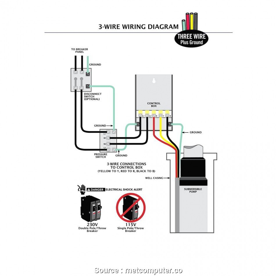
Typically, a well pump wiring diagram will include information on the power supply, control box, pressure switch, and pump motor. The diagram will show how these components are connected and the proper wiring configurations for each. Following the diagram carefully will help prevent damage to the pump and ensure it operates efficiently.
In addition to the well pump wiring diagram, it is important to use the correct size and type of wiring for your system. Using the wrong wiring can result in electrical issues, pump failure, or even fire hazards. Always refer to the manufacturer’s specifications and guidelines when selecting and installing wiring for your well pump.
Overall, a well pump wiring diagram is a valuable resource for anyone working with well pump systems. By following the diagram and using the proper wiring techniques, you can ensure that your well pump operates safely and effectively. If you are unsure about any aspect of the wiring process, do not hesitate to seek professional assistance to avoid any potential hazards.