USB (Universal Serial Bus) cables are commonly used to connect devices such as computers, cameras, smartphones, and more. Understanding the wiring schematic diagram of USB cables can help you troubleshoot connectivity issues and ensure proper connections.
USB cables typically consist of four wires – two for power (VCC and GND) and two for data (D+ and D-). Each wire plays a specific role in transmitting data and power between devices.
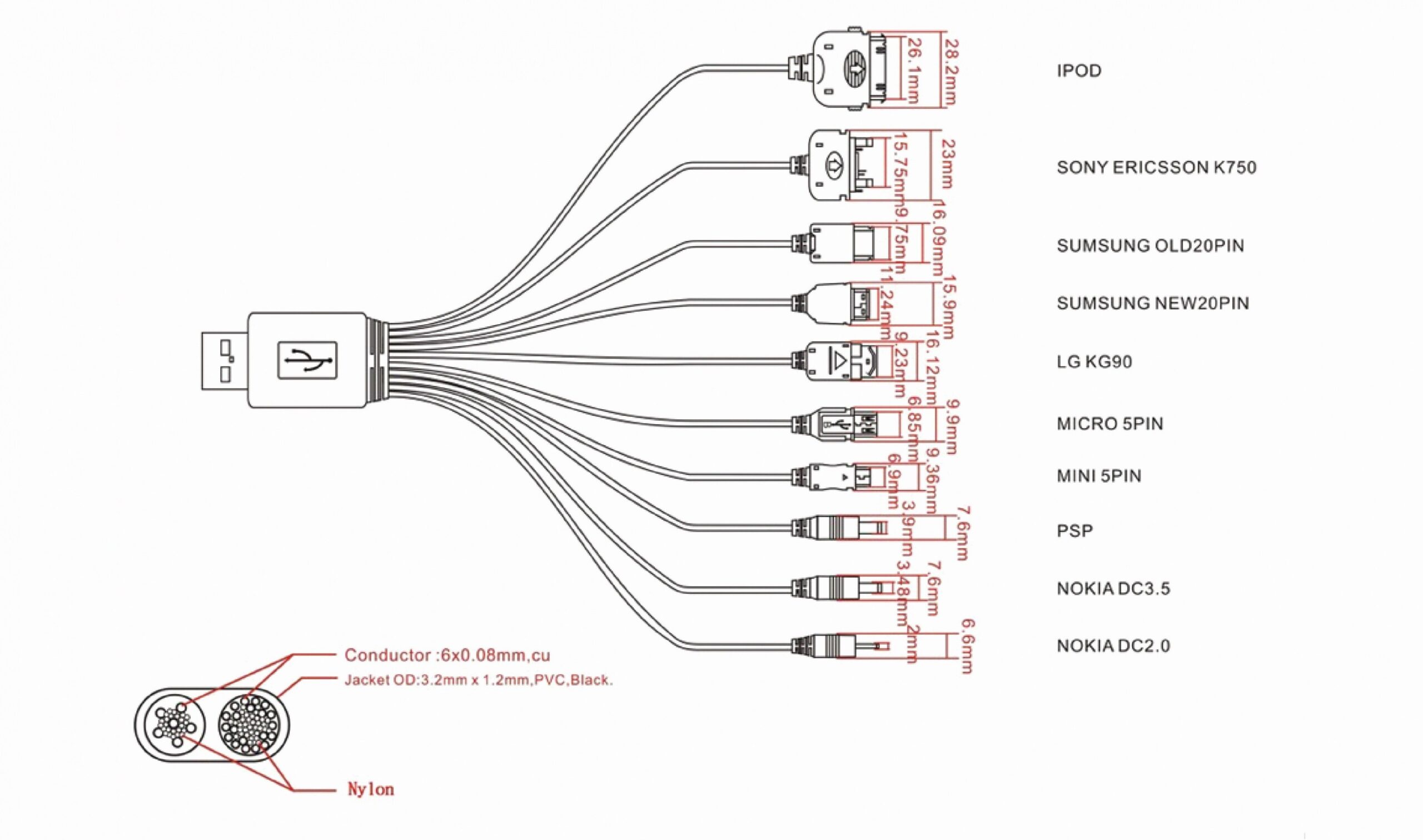
 Usb Cable Color Code Diagram Wiring Diagram Mini Usb Wiring Diagram (2020cadillac.com)
When looking at a USB wiring schematic diagram, you will see the four wires labeled accordingly. VCC (Voltage Common Collector) is the power wire that supplies 5V to the device. GND (Ground) is the wire that completes the circuit and provides a return path for the current.
The data wires, D+ and D-, are responsible for transmitting data between devices. D+ carries data signals from the host to the device, while D- carries data signals from the device to the host. It is important to ensure these data wires are connected correctly to establish a successful data connection.
In addition to the four wires, USB cables also have a fifth wire known as the shield. The shield wire helps reduce electromagnetic interference and ensures a stable connection between devices. It is typically connected to the metal casing of the USB connector.
When connecting USB cables, it is essential to pay attention to the wiring schematic diagram to avoid any connectivity issues. Incorrect connections can lead to data transfer errors, power supply problems, or even damage to the devices. Referencing the schematic diagram can help you identify and correct any wiring issues.
Overall, understanding the USB wiring schematic diagram is crucial for ensuring proper connections and troubleshooting connectivity problems. By familiarizing yourself with the roles of each wire and following the diagram, you can ensure a reliable and efficient data transfer between your devices.