Thermostats are essential components of heating and cooling systems in homes and buildings. They help regulate the temperature by turning the system on and off as needed. Understanding the wiring of a thermostat is important for proper installation and troubleshooting.
When it comes to thermostat wiring, it is crucial to follow the correct diagram to ensure that the system functions correctly. The wiring diagram provides a visual representation of how the thermostat is connected to the HVAC system, including the furnace, air conditioner, or heat pump.
 Honeywell Thermostat Wiring Instructions Diy House Help Wiring (2020cadillac.com)
Thermostat wiring typically consists of several colored wires that are connected to specific terminals on the thermostat and HVAC system. These wires may vary depending on the type of thermostat and system, so it is important to refer to the wiring diagram provided by the manufacturer.
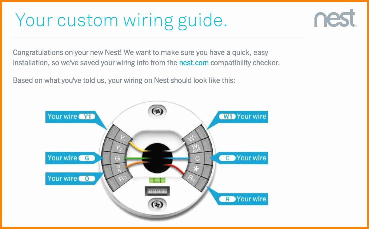
In a typical thermostat wiring diagram, you will see labels for the different terminals such as R (power), W (heat), Y (cool), G (fan), and C (common). The R wire is usually the 24-volt power supply, while the W wire is used for heating, the Y wire for cooling, the G wire for the fan, and the C wire for the common connection.
It is important to ensure that the wires are connected to the correct terminals on both the thermostat and HVAC system. Incorrect wiring can result in the system not functioning properly or even damage to the equipment. If you are unsure about the wiring or installation process, it is recommended to consult a professional HVAC technician.
In conclusion, understanding the thermostat wiring diagram is essential for proper installation and operation of heating and cooling systems. By following the diagram provided by the manufacturer and ensuring that the wires are connected correctly, you can ensure that your system functions efficiently and effectively.