USB (Universal Serial Bus) is a common type of connection used to transfer data and power between devices. It is important to understand how USB wiring works in order to properly connect devices and ensure they function correctly.
There are different types of USB connectors, including USB-A, USB-B, and USB-C. Each has its own wiring diagram, which dictates how the pins are connected and what functions they serve.
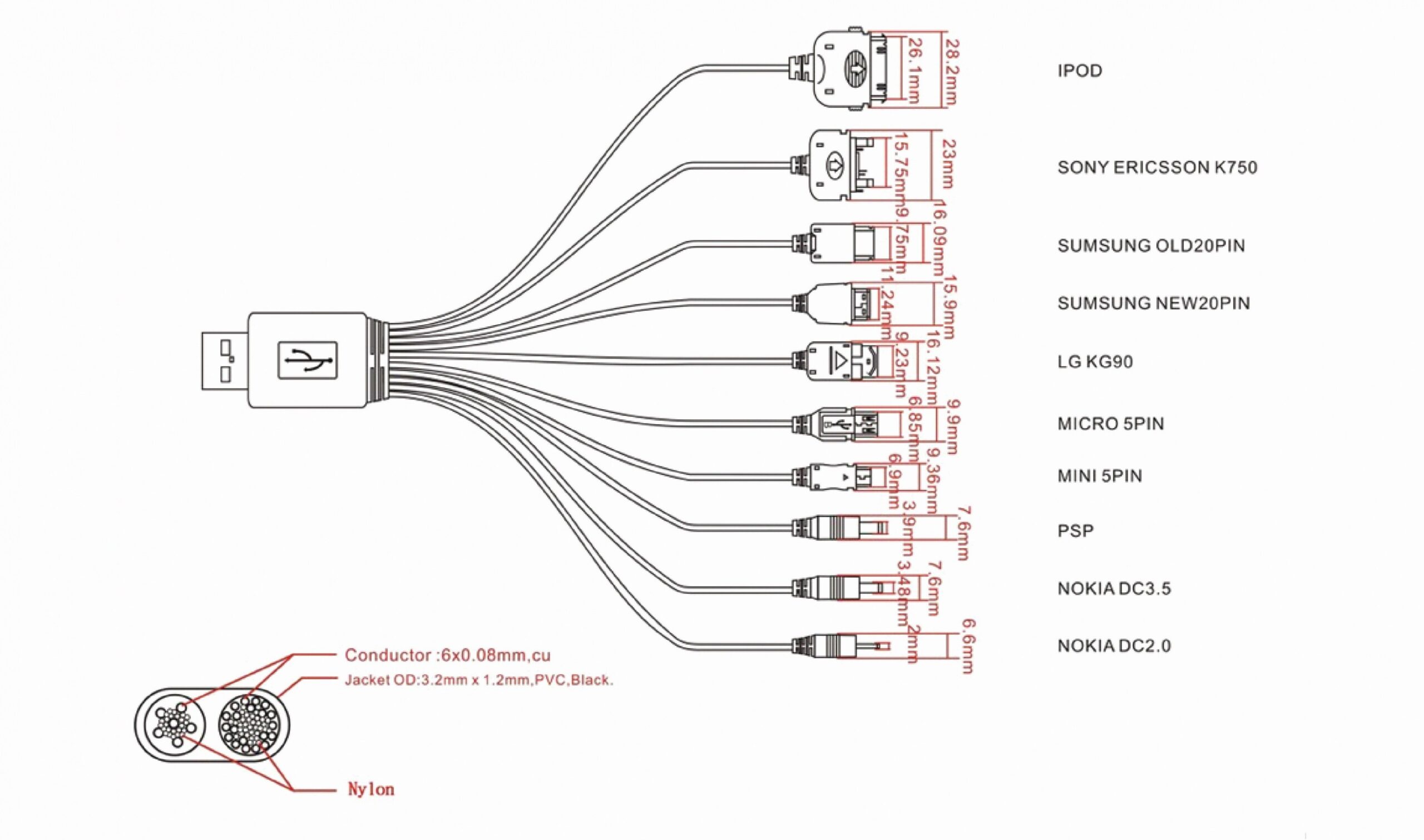
 Best Of Wiring Diagram Micro Usb Diagrams Digramssample (www.pinterest.ca)
USB Wiring Diagram
USB wiring diagrams typically show the pin connections for each type of USB connector. For example, a USB-A connector has four pins: VCC (power), D- (data negative), D+ (data positive), and GND (ground). These pins must be connected correctly in order for the device to function properly.
It is important to note that not all USB cables are wired the same way. Some cables may only be designed for charging, while others are capable of transferring data as well. It is crucial to check the wiring diagram of the cable before using it to connect devices.
When connecting USB devices, it is also important to consider the power requirements of each device. Some devices may require more power than others, which can impact how they are connected. Ensuring the correct wiring diagram is used will help prevent any issues with power distribution.
In addition to the physical wiring of USB connectors, it is also important to consider the software side of things. Proper drivers and firmware may be required in order for devices to communicate effectively over USB. It is important to follow the manufacturer’s guidelines when setting up USB connections.
Overall, understanding USB wiring diagrams is essential for properly connecting devices and ensuring they function correctly. By following the correct wiring diagrams and considering both the hardware and software aspects of USB connections, you can avoid potential issues and ensure a seamless experience when transferring data or power between devices.
