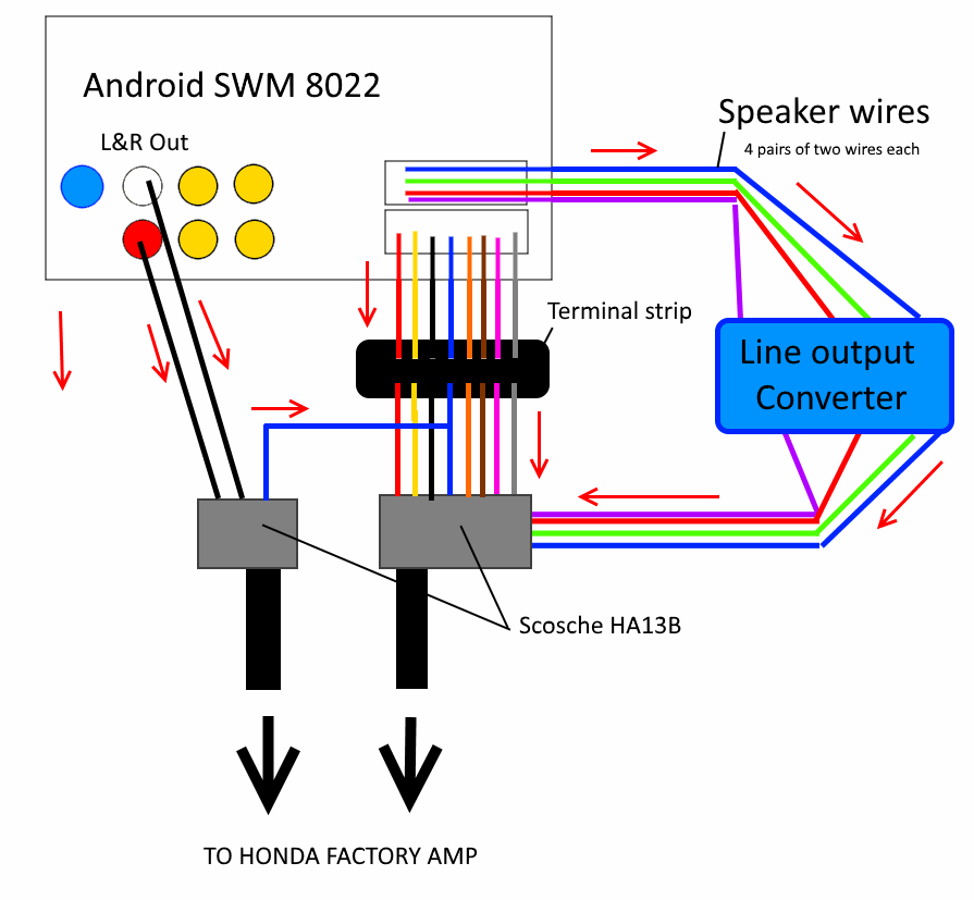
When installing a new car stereo system, you may need to use a Line Output Converter (LOC) to connect the existing factory stereo to your new aftermarket amplifier. A LOC converts speaker-level signals to line-level signals, which are needed for amplifiers to work properly. Understanding the wiring diagram for a LOC is crucial for a successful installation.
Before starting the installation process, it is important to gather all the necessary tools and materials, including the LOC, wiring harnesses, and electrical tape. Make sure to carefully read the instructions that come with the LOC to ensure proper wiring.
 Understanding Line Output Converter Wiring Diagrams Moo Wiring (moowiring.com)
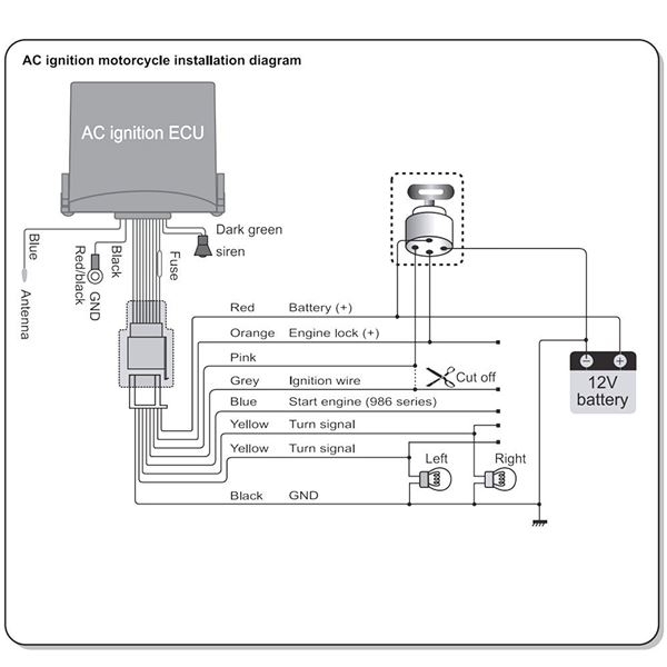
Here is a basic wiring diagram for a Line Output Converter:
1. Locate the speaker wires in the factory stereo that you will be tapping into. Most factory stereos have color-coded wires for easy identification. Connect the positive speaker wire to the positive input on the LOC and the negative speaker wire to the negative input on the LOC.
2. Connect the RCA cables from the LOC to the RCA inputs on your aftermarket amplifier. Make sure to connect the left and right channels correctly to avoid any sound issues.
3. Connect the remote turn-on wire from the amplifier to the remote turn-on output on the LOC. This wire is usually used to turn on the amplifier when the stereo is powered on.
4. Once all the connections are made, double-check everything to ensure that all wires are properly connected and secured. Use electrical tape to wrap any exposed wires to prevent short circuits.
In conclusion, understanding the wiring diagram for a Line Output Converter is essential for a successful car stereo installation. By following the steps outlined above, you can ensure that your new aftermarket amplifier works seamlessly with your factory stereo system. Always consult a professional if you are unsure about any part of the installation process.
