When it comes to networking, the RJ45 connector is essential for connecting devices to a local area network (LAN) or the internet. The RJ45 connector is commonly used for Ethernet connections and is designed to transmit data efficiently. To ensure a successful connection, it is important to have a clear understanding of the wiring diagram for the RJ45 connector.
The RJ45 connector has eight pins that need to be properly connected in order for data to be transmitted effectively. Each pin serves a specific purpose in the transmission of data, and following the correct wiring diagram is crucial for establishing a stable and reliable connection.
 Wiring Diagram Clipart Clipground (clipground.com)
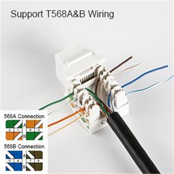
When wiring an RJ45 connector, it is important to adhere to the T568A or T568B wiring standards. These standards dictate the order in which the wires should be connected to the pins of the RJ45 connector. By following these standards, you can ensure that your network connection is set up correctly and that data can flow smoothly between devices.
To create a wiring diagram for an RJ45 connector, you will need to identify the color codes of the wires and match them to the appropriate pins on the connector. Typically, the wiring diagram will show the layout of the pins and the corresponding color codes for the wires, making it easy to follow and replicate for your own network setup.
By understanding the wiring diagram for an RJ45 connector and following the T568A or T568B standards, you can confidently set up network connections in your home or office. Whether you are connecting computers, printers, or other devices to your network, having a solid understanding of the RJ45 connector wiring will help ensure a smooth and reliable connection.
Overall, the wiring diagram for an RJ45 connector is an essential tool for anyone looking to set up a network connection. By following the proper standards and color codes, you can easily create a stable and efficient network setup that allows for seamless data transmission between devices.