Transformers are essential components in electrical systems that help to step up or step down voltage levels for various applications. Understanding how to wire a transformer correctly is crucial to ensure safety and efficiency in electrical installations. A transformer wiring diagram provides a visual representation of the connections required for proper installation.
Whether you are working on a residential, commercial, or industrial project, having a clear understanding of transformer wiring diagrams can help you avoid costly mistakes and ensure that the electrical system operates as intended. Let’s explore the key components of a transformer wiring diagram and how to interpret them.
 Honeywell 24 Volt Transformer Wiring Diagram New Wiring Diagram For (2020cadillac.com)
Components of a Transformer Wiring Diagram
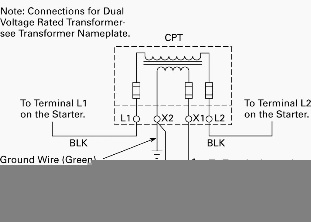
A typical transformer wiring diagram includes primary and secondary winding connections, as well as the terminals for grounding and protective devices. The primary winding is connected to the power source, while the secondary winding is connected to the load. The diagram also indicates the polarity of the windings and the direction of current flow.
Transformers may have multiple taps on the primary and secondary windings, allowing for voltage adjustments to suit specific requirements. The wiring diagram will show how to connect these taps for different voltage levels. Additionally, the diagram may include information on fusing, overcurrent protection, and grounding requirements to ensure safety and compliance with electrical codes.
Interpreting a transformer wiring diagram requires a basic understanding of electrical symbols and conventions. Common symbols used in wiring diagrams include lines to represent wires, dots to indicate connection points, and arrows to show the direction of current flow. It is essential to follow the diagram carefully and double-check all connections before energizing the transformer.
When wiring a transformer, it is crucial to use the correct wire sizes and insulation ratings to handle the expected current and voltage levels. Improper wiring can lead to overheating, voltage drops, or short circuits, posing a risk of fire or equipment damage. Following the manufacturer’s instructions and consulting a qualified electrician can help ensure a safe and reliable installation.
In conclusion, a transformer wiring diagram is a valuable tool for understanding the connections and configurations of transformers in electrical systems. By following the diagram accurately and adhering to safety guidelines, you can ensure proper installation and operation of transformers in various applications. If you are unsure about any aspect of transformer wiring, seek professional assistance to avoid potential hazards and ensure compliance with electrical regulations.