4 Pin Relay Wiring Diagram

Relays are essential components in electrical circuits, as they allow a low power signal to control a high power circuit. A 4 pin relay is used to control electrical devices such as fuel pumps, horns, headlights, and starter motors in vehicles. Understanding how to wire a 4 pin relay is crucial for proper functioning of these devices.

When wiring a 4 pin relay, it is important to understand the pin configuration. The four pins are typically labeled as follows: 30 (power), 85 (trigger), 86 (trigger), and 87 (output). Pin 30 is connected to the power source, while pins 85 and 86 are used to trigger the relay. Pin 87 is the output that is connected to the device being controlled.
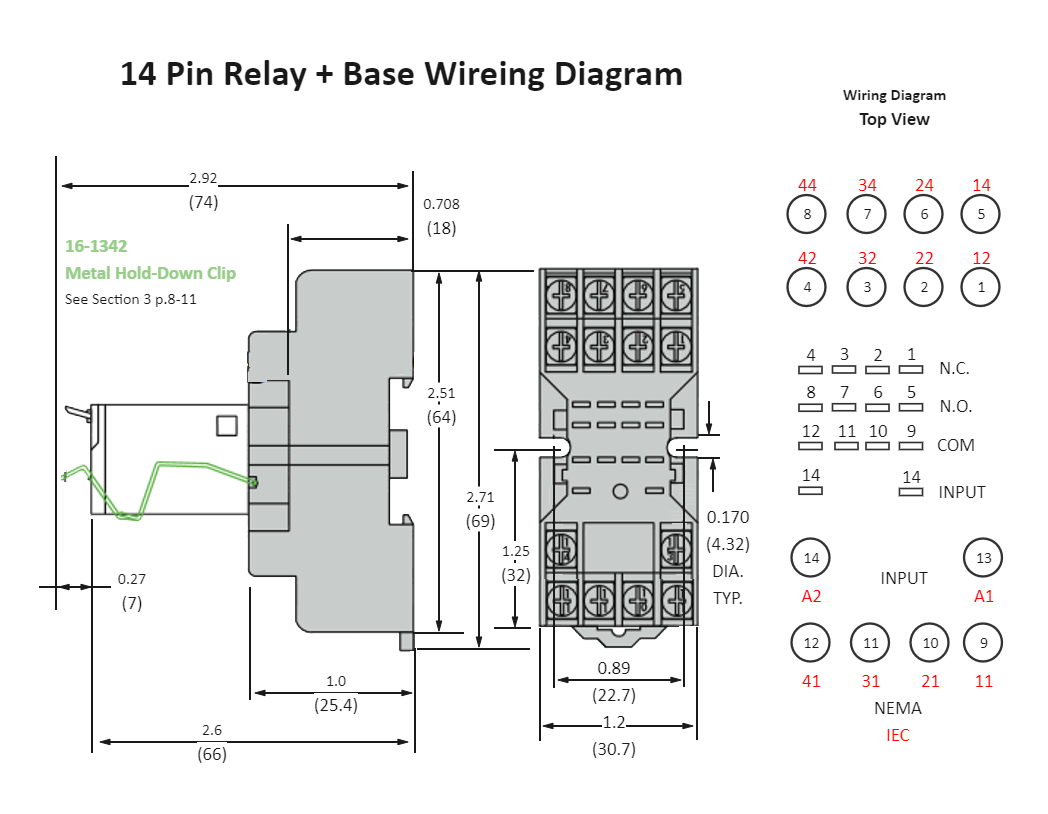
Wiring Diagram For 4 Pin RelayWiring Diagram For 4 Pin Relay (mungfali.com)

To wire a 4 pin relay, start by connecting pin 30 to the power source. This can be the battery or a fuse box. Next, connect pins 85 and 86 to the trigger source, such as a switch or the ignition. Make sure to use the appropriate gauge wire for the power and trigger connections. Finally, connect pin 87 to the device that needs to be controlled.

It is important to follow the wiring diagram provided with the relay to ensure proper installation. Incorrect wiring can result in damage to the relay or the device being controlled. Additionally, it is recommended to use a relay with a higher current rating than the device being controlled to prevent overload.

In conclusion, understanding how to wire a 4 pin relay is essential for controlling electrical devices in vehicles and other applications. By following the correct wiring diagram and using the appropriate gauge wire, you can ensure proper functioning of the relay and the devices it controls.


Download and Print 4 Pin Relay Wiring Diagram Listed below

9 Pin Relay Wiring Diagram Wiring Diagram9 Pin Relay Wiring Diagram Wiring Diagram (wiringdiagram.2bitboer.com)

12V 5 Pin Relay Wiring Diagram Webtor 12V Relay Wiring Diagram 5 12V 5 Pin Relay Wiring Diagram Webtor 12V Relay Wiring Diagram 5 (2020cadillac.com)

4 Pin Wiring Diagram Relay Wiring Diagram4 Pin Wiring Diagram Relay Wiring Diagram (wiring.ekocraft-appleleaf.com)

Omron Pin Relay Wiring Diagram Pin Relay Wiring Diagram 46 OFFOmron Pin Relay Wiring Diagram Pin Relay Wiring Diagram 46 OFF (conservacion.exactas.uba.ar)

4 Pin Relay Wiring Diagram Wiring Diagram4 Pin Relay Wiring Diagram Wiring Diagram (annawiringdiagram.com)

4 Pin Relay Wiring Diagram

Understanding 4 Pin Relay Wiring Diagram is more than just a technical skill — it’s a key advantage that can greatly enhance the accuracy, security, and efficiency of any electrical project. Whether you’re a casual user tackling DIY installations or a professional electrician dealing with complex circuits, the ability to read and interpret wiring diagrams accurately can save you time, prevent costly mistakes, and deliver better outcomes.

The 4 Pin Relay Wiring Diagram serve as a universal language in the world of electricity. They break down complex circuits, offer guidance during troubleshooting, and ensure that every connection is made with accuracy and intent. As electrical technology moves forward, having a solid understanding of these diagrams keeps you up to date and able to handle new technologies.

Remember, no matter your skill set, ongoing education is key. Study real-world examples, stay updated with industry standards, and don’t hesitate to get help when needed.

We appreciate your time for read 4 Pin Relay Wiring Diagram. We hope it provided useful knowledge of wiring diagrams and their importance. Be sure to browse our other guides to continue learning more in electrical work and beyond.