When it comes to wiring a 5 pin rocker switch, it’s important to understand the basic principles to ensure proper functionality. A rocker switch is a type of on/off switch that rocks back and forth to control power flow. These switches are commonly used in automotive and marine applications.
Before you start wiring your 5 pin rocker switch, make sure you have the necessary tools and materials on hand. This includes wire strippers, a soldering iron, solder, electrical tape, and of course, the rocker switch itself. It’s also important to have a clear understanding of the switch’s wiring diagram to avoid any mistakes.
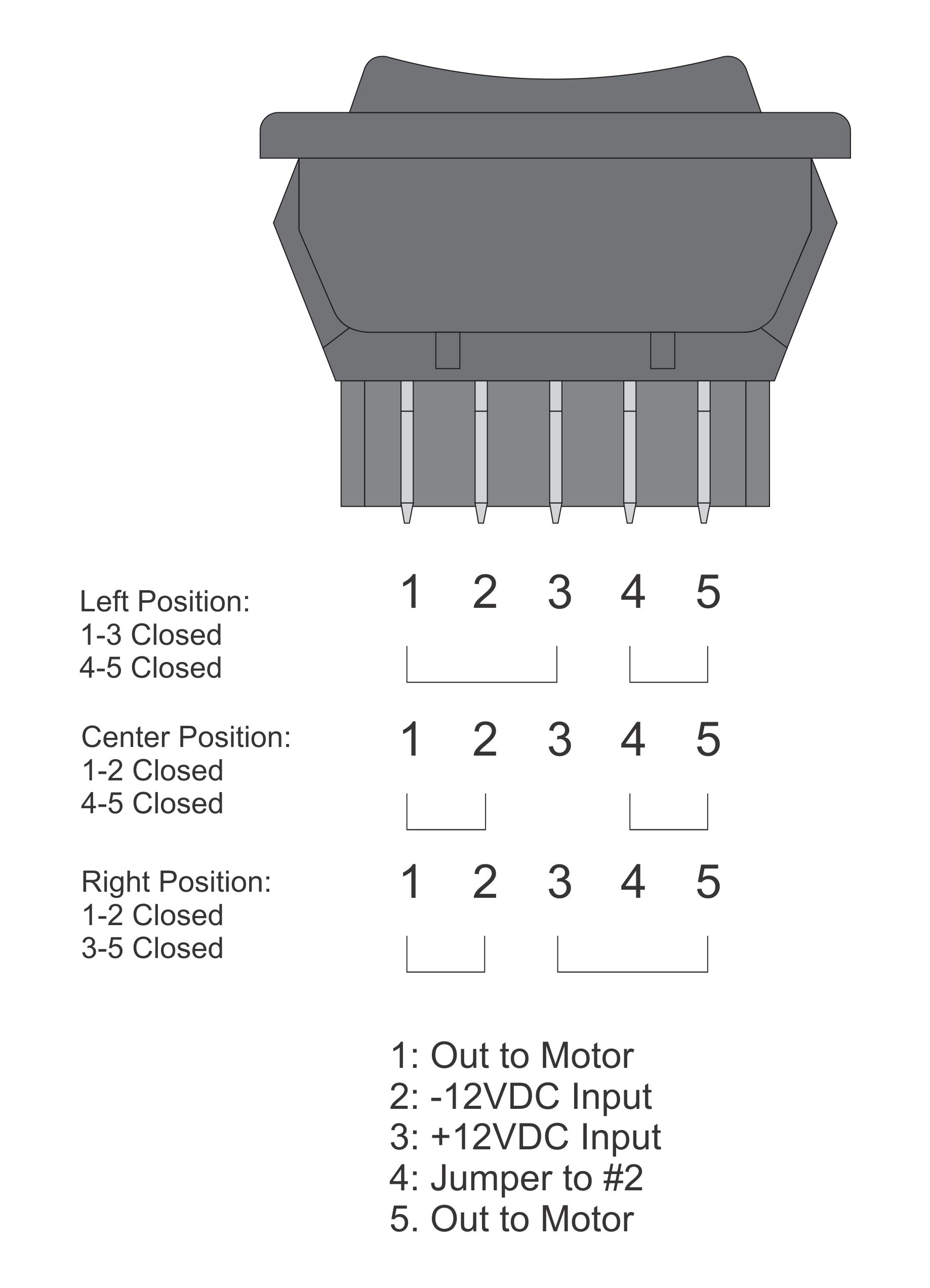
 Rocker Switch Wiring Diagram 5 Pin Esquilo Io (esquilo.io)
Begin by identifying the five pins on the rocker switch. These pins are typically labeled “1,” “2,” “3,” “4,” and “5.” Pin 1 is usually the power input, while pins 2 and 3 are the output connections. Pins 4 and 5 are often used for the switch’s backlight illumination, if applicable.
Next, connect the power source to pin 1 of the rocker switch. This can be done by soldering a wire from the positive terminal of the power source to pin 1. Then, connect pins 2 and 3 to the device you want to control with the switch. Make sure to solder these connections securely to ensure a reliable connection.
If your rocker switch has backlight illumination, connect pins 4 and 5 to the appropriate power source for the backlight. This will typically be the positive terminal of the power source. Once all connections are made, double-check your wiring to ensure everything is correct before testing the switch.
In conclusion, wiring a 5 pin rocker switch is a straightforward process as long as you follow the proper diagram and guidelines. With the right tools and materials, you can easily install a rocker switch in your vehicle or boat to control various devices. Remember to always prioritize safety and double-check your connections before powering up the switch.
