USB ports are an essential component of modern devices, allowing for the transfer of data and power between devices. Understanding the wiring diagram of a USB port can help in troubleshooting connectivity issues and ensuring proper functionality.
With the increasing use of USB ports in various devices, it is important to know how they are wired to ensure compatibility and proper functioning. A USB port wiring diagram provides a visual representation of the connections and pins involved in a USB port.
 Usb Port Wiring (circuitdiagramgooden.z19.web.core.window…)
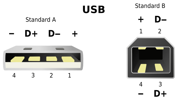
USB Port Wiring Diagram
A standard USB port consists of four pins – VCC (power), D- (data negative), D+ (data positive), and GND (ground). These pins are connected to corresponding wires inside the USB cable, which are then connected to the USB port on the device.
When a USB device is connected to a port, the VCC pin provides power to the device, while the D- and D+ pins are used for data transfer. The GND pin serves as the reference point for the electrical circuit, ensuring proper grounding and signal integrity.
It is important to follow the correct wiring diagram when connecting USB ports to devices to avoid damaging the port or the device. Incorrect wiring can result in short circuits, data loss, or device malfunction.
By understanding the wiring diagram of a USB port, users can troubleshoot connectivity issues, identify faulty connections, and ensure proper data transfer and power delivery between devices. This knowledge can help in maintaining the longevity and functionality of USB ports in various devices.
In conclusion, a USB port wiring diagram is a valuable tool for understanding the connections and pins involved in a USB port. By following the correct wiring diagram, users can ensure proper functionality, compatibility, and reliability of USB ports in their devices.