Single-phase motors are commonly used in various applications such as fans, pumps, and compressors. These motors require a capacitor to start the motor, and if you are looking for a wiring diagram with capacitor start, you have come to the right place.
Understanding the wiring diagram for a single-phase motor with capacitor start is essential for proper installation and operation. The diagram provides a visual representation of how the motor should be connected to the power source and the capacitor to ensure correct functioning.
 Single Phase Fan Wiring Diagram With Capacitor Wiring Diagram And (diagram.tntuservices.com)
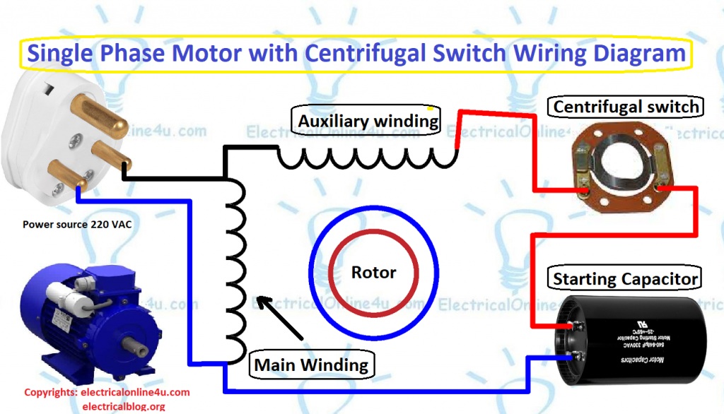
When looking at the wiring diagram, you will typically see the main winding, auxiliary winding, capacitor, and starting switch. The main winding is connected directly to the power source, while the auxiliary winding and capacitor are connected in series with the starting switch. This configuration provides the necessary phase shift to start the motor.
It is important to follow the wiring diagram carefully to avoid any errors that could potentially damage the motor or pose a safety hazard. If you are unsure about how to wire the motor with a capacitor start, it is recommended to seek the assistance of a professional electrician.
By referring to a single-phase motor wiring diagram with capacitor start PDF, you can easily understand the connections required for proper installation. This diagram serves as a valuable resource for anyone working with single-phase motors and ensures that the motor operates efficiently and safely.
In conclusion, a wiring diagram for a single-phase motor with capacitor start is crucial for successful installation and operation. By following the diagram accurately, you can avoid potential issues and ensure that the motor functions as intended. Be sure to consult the PDF diagram for reference and seek professional help if needed.