Reliance transfer switches are essential components in backup power systems, allowing you to easily switch between utility power and generator power during an outage. Understanding the internal wiring diagram of a reliance transfer switch is crucial for proper installation and maintenance.
Reliance transfer switches come in various models and sizes, but they all have similar internal wiring components. The internal wiring diagram provides a detailed illustration of how the switch connects to the utility power, generator, and the electrical panel in your home.
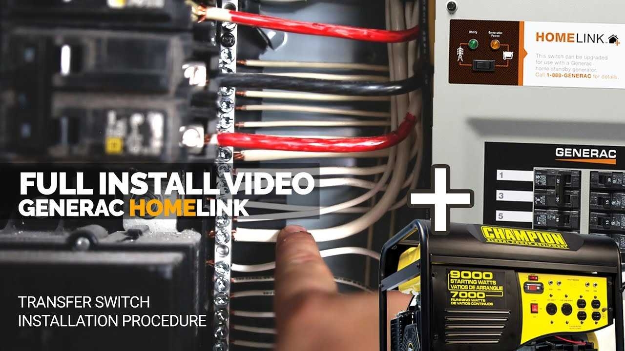
 Reliance Transfer Switch Wiring Diagram (stewart-switch.com)
One key component in the internal wiring diagram is the utility power input, which is connected to the transfer switch to provide power to the electrical panel when utility power is available. The generator input is another important component, allowing the switch to transfer power from the generator to the electrical panel during an outage.
The internal wiring diagram also includes connections for the transfer switch control wires, which are used to monitor the status of utility power and generator power. These control wires ensure that the switch operates correctly and transfers power seamlessly between sources.
It’s important to follow the internal wiring diagram provided by the manufacturer when installing or troubleshooting a reliance transfer switch. Incorrect wiring can lead to power failures, damage to the switch, and even safety hazards. If you’re unsure about the wiring or installation process, it’s best to consult a professional electrician.
In conclusion, understanding the internal wiring diagram of a reliance transfer switch is essential for ensuring the proper operation of your backup power system. By following the diagram provided by the manufacturer and seeking help from a professional if needed, you can rest assured that your transfer switch will provide reliable power during outages.