When it comes to electrical safety in your home, one of the most important devices you can have is a Ground Fault Circuit Interrupter (GFCI) outlet. These outlets are designed to protect against electrical shock by quickly shutting off power when a fault is detected. Understanding the wiring diagram for a GFCI outlet is crucial for proper installation and maintenance.
Installing a GFCI outlet is a relatively simple process, but it is essential to follow the correct wiring diagram to ensure it functions properly. The diagram typically includes a line connection, a load connection, and a ground connection. It is crucial to understand which wires go where to prevent any issues with the outlet.
 Gfci Outlet Wiring Diagram Database (www.got2bwireless.com)
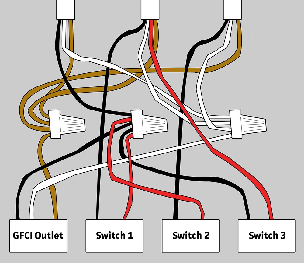
GFCI Outlet Wiring Diagram
The line connection is where the power source is connected to the GFCI outlet. This connection is typically marked with a “LINE” label on the outlet. The load connection, on the other hand, is where additional outlets or devices are connected for protection by the GFCI. It is important to connect the wires correctly to prevent any malfunctions.
Another important aspect of the GFCI outlet wiring diagram is the ground connection. This connection ensures that any excess electricity is safely directed away from the outlet. It is crucial to have a proper ground connection to prevent electrical shocks and potential damage to the outlet.
It is also essential to test the GFCI outlet regularly to ensure it is functioning correctly. Testing the outlet involves pressing the test button to simulate a fault and ensure that the GFCI shuts off power as intended. If the outlet does not trip, it may indicate a wiring issue that needs to be addressed.
In conclusion, understanding the wiring diagram for a GFCI outlet is crucial for ensuring electrical safety in your home. Proper installation and maintenance of these outlets can help prevent electrical shocks and protect your home from potential hazards. By following the correct wiring diagram and testing the outlet regularly, you can ensure that your GFCI is functioning properly and keeping you safe.