Water well pump wiring diagrams are essential for anyone looking to install or replace a well pump. These diagrams provide a clear outline of how the pump should be wired to ensure proper functioning and safety.
Understanding the wiring diagram is crucial for proper installation to avoid any potential hazards or malfunctions. It is recommended to seek professional assistance if you are unsure about the wiring process.
 Submersible Well Pump Wiring Diagram Printable Form Templates And Letter (projectopenletter.com)
Components of a Water Well Pump Wiring Diagram
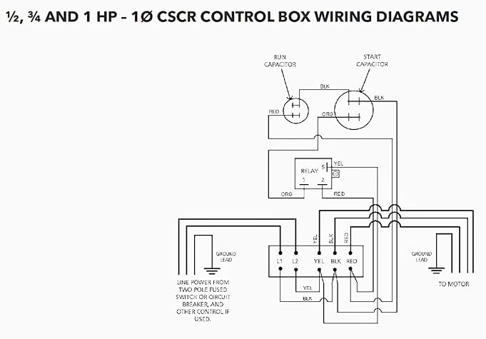
A typical water well pump wiring diagram consists of various components such as the pump motor, pressure switch, control box, and power supply. Each component plays a crucial role in the functioning of the well pump and must be wired correctly to ensure smooth operation.
The pump motor is responsible for pumping water from the well to the surface. It is connected to the power supply through the control box, which regulates the flow of electricity to the motor. The pressure switch controls the on/off function of the pump based on the water pressure in the system.
Proper wiring of these components is essential to prevent any electrical issues or damage to the pump. It is important to follow the wiring diagram carefully and double-check all connections before powering up the pump.
Consulting a professional electrician or well pump technician is recommended if you are unfamiliar with wiring diagrams or are unsure about the installation process. They can provide guidance and ensure that the pump is wired correctly for optimal performance.
In conclusion, water well pump wiring diagrams are essential for the proper installation and functioning of a well pump. Understanding the diagram and wiring the components correctly is crucial to avoid any potential hazards or malfunctions. Seek professional assistance if needed to ensure a safe and successful installation.