When it comes to networking, the RJ45 connector is a key component for connecting devices to a local area network (LAN) or the internet. It is commonly used for Ethernet connections in homes, offices, and data centers. Understanding how to wire an RJ45 connector correctly is essential for ensuring a reliable and secure network connection.
The RJ45 connector wiring diagram provides a visual representation of how the wires inside the connector should be arranged. This diagram is crucial for proper installation and troubleshooting of network cables. By following the wiring diagram, you can ensure that the connection is correctly made and that data can be transmitted efficiently.
 Rj45 Connector Wiring Diagram AndersGarnow (www.andersgarnow.com)
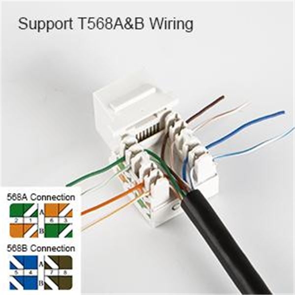
Typically, an RJ45 connector has eight pins, which are used to connect eight individual wires. These wires are typically color-coded to make it easier to identify and connect them correctly. The wiring diagram will show you which wire should be connected to each pin on the RJ45 connector.
It is important to note that there are two main standards for wiring RJ45 connectors – T568A and T568B. The wiring diagram will specify which standard should be used for your particular network setup. Using the correct wiring standard is crucial for ensuring compatibility with other network devices and equipment.
Once you have correctly wired the RJ45 connector, you can crimp the connector onto the end of the network cable using a crimping tool. This will secure the wires in place and create a reliable connection. It is important to test the connection using a network tester to ensure that data can be transmitted successfully.
In conclusion, understanding the RJ45 connector wiring diagram is essential for setting up a reliable and secure network connection. By following the diagram and using the correct wiring standard, you can ensure that your network cables are properly connected and that data can be transmitted efficiently. Properly wired RJ45 connectors are essential for maintaining a stable network connection and preventing connectivity issues.