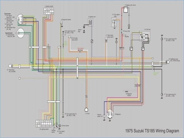
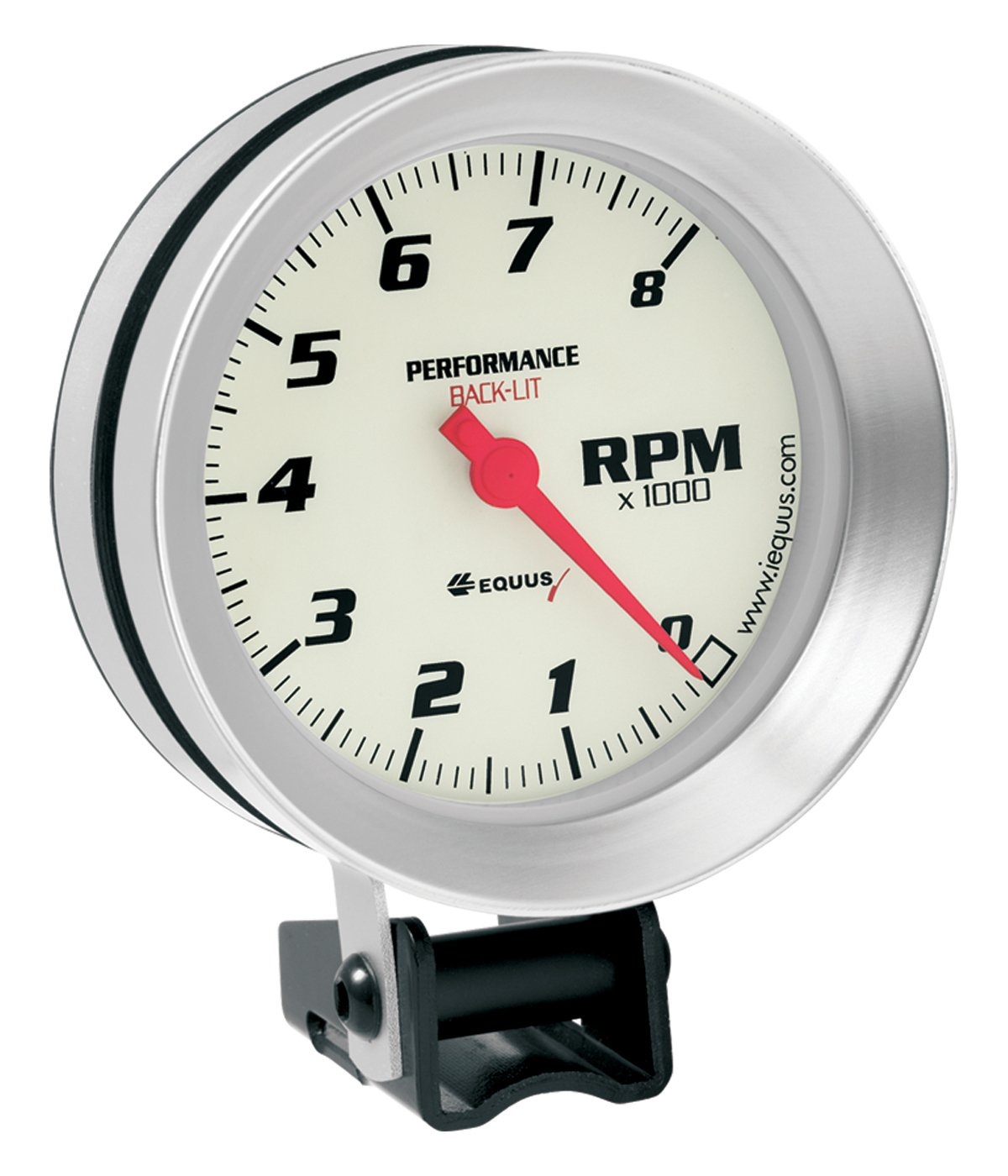
When it comes to installing a tachometer in your vehicle, understanding the wiring diagram is essential to ensure proper functionality. A tachometer is a device that measures the rotation speed of the engine’s crankshaft, which helps you monitor the performance of your vehicle. By following the wiring diagram correctly, you can easily connect the tachometer to your vehicle’s ignition system and get accurate readings.
Whether you are installing a tachometer for performance tuning or simply to keep track of your engine’s RPM, having a clear understanding of the wiring diagram is crucial. The diagram typically includes the color-coding of wires, the connection points, and any additional components needed for proper installation. By following the diagram step by step, you can avoid any errors and ensure that your tachometer works correctly.
 Suzuki Outboard Tachometer Wiring Diagram (stewart-switch.com)
First, locate the ignition coil or distributor in your vehicle, as this is where you will be connecting the tachometer. The wiring diagram will indicate which wires need to be connected to the ignition system, typically the signal wire, power wire, and ground wire. It’s important to connect these wires securely and make sure they are properly insulated to prevent any short circuits.
Next, refer to the wiring diagram to identify any additional components that may be required for the tachometer installation, such as a tachometer adapter or resistor. These components are often necessary to ensure compatibility with your vehicle’s ignition system and to provide accurate readings. Make sure to follow the manufacturer’s instructions for installing these components correctly.
Once all the wires and components are connected according to the wiring diagram, test the tachometer to ensure that it is working properly. Start the engine and observe the readings on the tachometer display to verify that it is accurately measuring the engine’s RPM. If there are any issues, double-check the wiring connections and consult the wiring diagram for troubleshooting tips.
In conclusion, understanding the tachometer wiring diagram is essential for a successful installation in your vehicle. By following the diagram carefully and making sure all connections are secure, you can enjoy the benefits of having a reliable tachometer to monitor your engine’s performance. With proper installation and maintenance, your tachometer will provide you with valuable information to help you optimize your vehicle’s performance.
