When it comes to wiring a 3-phase motor, it is important to follow the correct diagram to ensure the motor operates correctly and safely. 3-phase motors are commonly used in industrial applications due to their efficiency and power output. Understanding the wiring diagram is crucial for proper installation and maintenance of these motors.
Before attempting to wire a 3-phase motor, it is important to have a clear understanding of the different components and how they are connected. The wiring diagram will provide a visual representation of how the motor is wired, including the connections for the power supply, start and stop buttons, and any other necessary components.
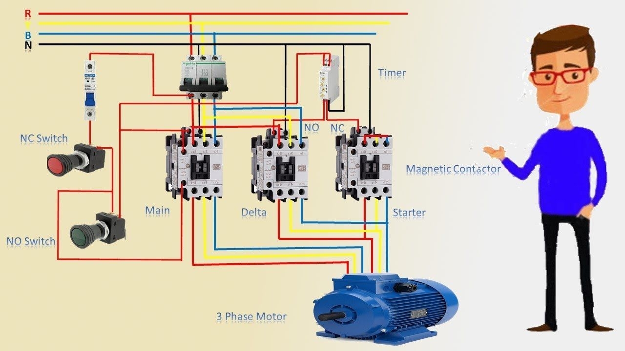
 3 Phase Motor Wiring Diagram Explained For Beginners (schempro.com)
One of the most common wiring diagrams for a 3-phase motor is the star-delta configuration. This diagram shows how the motor windings are connected in both a star and delta configuration, allowing for different speeds and power outputs. Understanding this diagram is essential for troubleshooting and maintenance of the motor.
Another important aspect of wiring a 3-phase motor is ensuring that the correct wire sizes and connections are used. Using the wrong wire size or improperly connecting the wires can lead to overheating, short circuits, and other potential hazards. Following the wiring diagram carefully will help prevent these issues and ensure the motor operates safely.
In conclusion, understanding the wiring diagram for a 3-phase motor is essential for proper installation and maintenance. By following the correct diagram and using the appropriate wire sizes and connections, the motor can operate efficiently and safely. Whether it is a star-delta configuration or another wiring setup, taking the time to study and follow the diagram will help ensure the motor functions as intended.